
EEVblog® Electronics Community Forum
EEVblog® Electronics Community Forum

A Free & Open Forum For Electronics Enthusiasts & Professionals
Welcome, Guest. Please login or register. Did you miss your activation email?
Login with username, password and session length
-
 Home
-
 Help
-
 Search
- About us
- Links
-
 Login
-
 Register
- EEVblog® Electronics Community Forum »
- Electronics »
- Projects, Designs, and Technical Stuff »
- Medical implant teardown: intro & Intermedics Interlith 224 pacemaker
- Search
- Frequent Contributor
- Posts: 386
- Country:

- Fixed oscillator: The simplest way to regulate a heartbeat is with a simple fixed-frequency oscillator driving the heart. The first implanted pacemaker used a 2-transistor circuit (click for technical analysis), and other early models use only a handful of discrete transistors. There's an example of a 60's discrete-transistor model here.
- Fixed oscillator with inhibit: However, the heart usually doesn't need the pacemaker's help on every heartbeat, and so delivering pulses only when necessary is a great way to save a lot of battery power. Power consumption is one of the biggest constraints on pacemakers, as higher power requires either more space within the patient's chest (already very limited), or more frequent surgeries to replace the pacemaker when the batteries get low (unpleasant, expensive, and risks complications every time). With increased electronic miniaturization, pacemakers started incorporating "inhibit" functions, where the lead would work as an input too, to detect the low voltage pulse of a naturally-occurring muscle contraction: the pacemaker would only deliver a pulse if a natural heartbeat wasn't detected within a "normal" time window.
- Programmable oscillator with inhibit: One size does not fit all when it comes to heart rate. Resting heart rates, when the heart is working properly, can vary a lot between different people depending on factors like physical condition or age. Therefore, once fairly complex digital circuitry could be fit within pacemakers (I believe sometime around the late 70's), they started incorporating telemetry and programmability. Using a coil to communicate via inductive coupling, doctors could use external programmers to both set the desired heart rate and also read back diagnostics.
- Variable oscillator with inhibit: The next step up in complexity is to vary the target heart rate depending on the body's current needs, just as the body does itself when working correctly. The heart rate normally follows the demand for oxygen, pumping more or less blood as needed, to support a variety of activity levels. With a pacemaker's fixed heart rate set at a resting level, it's difficult or impossible for the patient to do anything (like exercise) that requires more oxygen delivered to either the muscles or brain. Activity-sensing pacemakers with variable target heart rates seem to have started appearing in the mid-80's and became standard over time. There are a few methods to estimate how much oxygen is needed, and therefore what heart rate is needed: temperature sensing in the heart I think is the most accurate, but is unpopular because it requires an additional lead stuck into the heart. Sensing breathing rate by measuring chest pressure, and patient movement with an accelerometer, are much easier and therefore popular even though movement is not directly correlated with oxygen demand. Now with some background information under our belt, let's take a look at this specific device: Intermedics Interlith 224 Pacemaker
- The op-amps used here are both LM4250s (datasheet), which I recognized from a teardown of (spoilers) a later Intermedics pacemaker. This is an interesting part with its internal current sources programmed through a single external resistor: this allows setting the power-vs-bandwidth tradeoff anywhere within a wide range. Despite being a bipolar part, it can consume a surprisingly small current (\~1 µA with a 100 nA bias current setting), and can run on power supplies as low as 3V / ±1.5V - unusual for many other op-amps of the time which only work well on 10V or 20V. This makes it a good choice for a pacemaker, where only a very low 2.8V supply is available, and where signals are extremely low frequency (minimal bandwidth needed) but low power consumption is critical. The LM4250 was likely too niche at the time to come in a commercially-available dual die version, which is why 2 dies were co-packaged in the custom National Semiconductor hybrid.
- The circuit design is sketchier than I would've expected for something life-or-death like this. Specifically, the NAND gate inputs are used with slow-changing analog voltages in both the oscillator (U4B pin 5) and heartbeat detector (U3D pin 13). I would've expected Schmitt-trigger inputs, especially for the heartbeat input which has no defined thresholding via a comparator or anything similar - even the variable threshold (between parts, with temperature, etc.) of a Schmitt-trigger input at least creates a solid "tipping point", even if the exact value doesn't matter. I assume that the gain is high enough on the amplifiers though, that it's more than enough to saturate the U2 output at the rail during a heartbeat. I also assume that the behavior of these particular CMOS parts must've been carefully characterized with slow-changing inputs; at least slow, simple 4000-series CMOS (even the standard parts) is much better-behaved with slow inputs than 74HC-series logic. As a follow-up, take a look at this teardown of a newer InterLith-RP from Mike's Electric Stuff. This is the "rate-programmable" model, with a big copper coil for external communications. You can see a similar-looking set of CMOS gates and timers on stacked circuit boards, but with (I think) a 4-bit counter or two which may be part of a digitally-programmable oscillator. The other noticeable addition is the big Rockwell hybrid circuit, which contains a variety of circuitry likely for the communications and programming.
- Super Contributor
- Posts: 2109
- Country:
- Search
- EEVblog® Electronics Community Forum »
- Electronics »
- Projects, Designs, and Technical Stuff »
- Medical implant teardown: intro & Intermedics Interlith 224 pacemaker
- SMF 2.0.19 | SMF © 2021, Simple Machines Simple Audio Video Embedder SMFAds for Free Forums | Powered by SMFPacks Advanced Attachments Uploader Mod
- XHTML
- RSS
- Mobile
- Mobile
- WAP2


Pages: \[1\] Go Down
 AuthorTopic: Medical implant teardown: intro & Intermedics Interlith 224 pacemaker (Read 669 times)
D Straney and 36 Guests are viewing this topic.
####  D Straney


##### Medical implant teardown: intro & Intermedics Interlith 224 pacemaker
« on: August 02, 2026, 06:36:32 pm »
I've been interested in medical implants (pacemakers, implantable defibrillators, neurostimulators, cochlear implants, etc.) for a while because of their extreme requirements for miniaturization, low power, and reliability all at once - but didn't think I'd be able to get my hands on any. However, inspired by a recent post from Noopy/Richi about a Medtronics ICD, I went poking around and was able to find people getting rid of their old implants on eBay for cheap: therefore, teardowns! Background for cardiac implants Before getting into the specifics of this particular device, let's talk a bit about the basics of heart-related implants so you know how most of these devices are supposed to behave (as the cardiac devices are by far the most common). I am very much not an expert on hearts or medicine in general, so take everything I say with a grain of salt, and let me know if I got something wrong. Pacemakers: The heart has its own neural oscillator circuitry, which commands the different sets of heart muscles to coordinate the multi-phase blood pumping operation. The frequency is controlled by various factors like oxygen demand, stress, etc. Many things can go wrong with this neural oscillator that cause a heartbeat that is too fast, or too slow, or maybe skips beats sometimes. A pacemaker is meant to correct these types of conditions by overriding the heart's own muscle contraction signals when necessary, and ensuring a steady heartbeat at a useful rate. Leads are implanted into one or more places in the heart: because these are making direct contact with the muscles, only low-voltage low-current pulses are needed to activate the heart muscles. Pulses are typically in the ballpark of 5V & 10 mA. Implantable defibrillators & ICDs: Ventricular or atrial fibrillation is a separate and much more dangerous type of dysfunction where the heart's neural oscillator loses synchronization completely, and instead of producing any kind of recognizable rhythm, "thrashes around" with weak, random muscle contractions that do not pump blood. Implantable defibrillators are meant to detect and fix this situation, as this will obviously kill you very quickly compared to the more long-term problems solved by a pacemaker. Implantable defibrillators are often combined with pacemaker functionality into what's known as an ICD (Implantable Cardioverter-Defibrillator). A defibrillator needs to not just activate the heart muscles, like with a pacemaker, but give a high-energy shock to completely reset the neural oscillator and break it out of its non-functioning state. Typical pulses here, according to Noopy's post referenced at the beginning, are more like 800V & 20A peak. To summarize: from an electrical point of view, pacemakers deliver small pulses regularly, while defibrillators deliver large pulses occasionally. We'll see throughout these analyses of different devices how this affects the circuitry. Pacemaker features & complexity External pacemakers existed in the vaccuum tube era, but having to carry around something with leads that pierce the skin creates a whole set of difficulties that make a normal life impossible. The first implantable pacemaker was used in 1958, as transistors were becoming common and reliable enough to make this possible. Over time, the complexity and functionality of pacemakers has of course grown as electronics has advanced. Here's the rough stages of development, and what you can expect in pacemakers of different eras:

 According to implantable-device.com, Intermedics has been around since 1973, and the Interlith series was introduced in 1976. We'll see later when we look at the circuitry that this one falls into the "fixed oscillator with inhibit" category.
As is common, the housing consists of a sealed titanium shell and some type of transparent silicone connector for the heart leads. These are chosen for their biocompatibility, as there's a very limited set of materials that can be put inside the body without causing issues. (I have a threaded rod inside my hand which is either titanium or a specific type of stainless steel) You can see the hermetic feed-throughs that bring the lead connections from the sealed can out to the contacts in the connector.
 Now, when opened:
 The bottom half is taken up by the (non-rechargeable) lithium battery. There's a lot of material out there on different pacemaker battery chemistries as R&D on pacemaker batteries for density is its own very deep rabbit hole, but that's not really what I'm interested in, so just a couple quick points: these are not modern lithium-ion batteries, and they have a high internal resistance as they're meant for small currents and low self-discharge over a few years. This is most likely a lithium-iodide chemistry, with an open-circuit voltage of 2.8V. There's 2 straps spot-welded to the battery and connected to the housing at the top, which I think are there as mechanical support and to keep the battery's case at outside potential ("body ground").
 Let's cut those straps and fold them back so we can see the top half, which contains the electronics. This is a masterpiece of 3D stacking, with 3 separate circuit boards:
 These boards are stacked closely, separated with insulators, and connected together electrically with pins that span either 2 or 3 at a time. Some of these inter-board pins are also the battery and lead connections.

 There's a couple "floating" capacitors, which are connected between each external lead, and the metal housing (which is the equivalent of "earth ground" when inside the body).
 By carefully cutting some of the pins and bending the others, I was able to get a closer look at the circuitry. Here's each of the circuit boards in turn:
Digital board
 This board contains standard 4000-series CMOS logic, but in ceramic-and-metal "flatpack" packages that are usually found in 60's and 70's military equipment & avionics. The one visible date code is 1977, which makes sense with the 1976 Interlith introduction date; this must've been a fairly early model in the production run.
The "SSS" logo on the ICs stands for Solid State Scientific. You can read a 1984 databook of their standard CMOS logic ICs at bitsavers. They seem to specialize in high-reliability applications judging by the packaging choices available, which makes sense as a niche for a smaller company as there's not much point in competing with giants like Texas Instruments, Fairchild, etc. on commodity parts.
Analog board
 This has a single IC with a National Semiconductor logo, but a non-standard part number - "SH" indicates a 'special' hybrid. When opened, it turns out to contain 2 individual op-amp dies:

 Power board
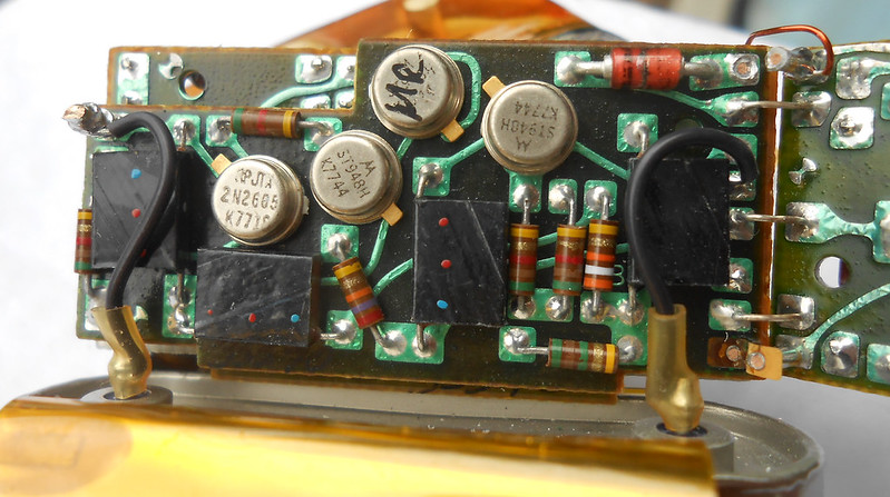 All the metal cans on this board are the transistors responsible for delivering the output pulses.
Now, with all the boards visible, I traced the circuitry:
« Last Edit: August 02, 2026, 09:33:26 pm by D Straney »
 Logged
The following users thanked this post: NF6X, 42Khz
---
####  Seekonk

##### Re: Medical implant teardown: intro & Intermedics Interlith 224 pacemaker
« Reply #1 on: Today at 01:18:15 pm »
I have one. By initial calculation the battery should be dead by now. That design is so quaint (1977 from date codes), carbon comp resistors! Back in the very late 60's my mentor was head of biomedical engineering at a teaching hospital. He made external pacemakers out of metronomes, the ones found in the back of Popular Mechanics for $1.99 and potted in a cupcake tin. I was shocked knowing the surplus and sub par transistors these were made out of. I asked him if he worried about these failing and that lives could be lost. He said the patients were all on monitors and wasn't an issue. I got to see many technical innovations that didn't show up till many years later.
Logged
The following users thanked this post: D Straney
---
Pages: \[1\] Go Up
Share me


There was an error while thanking
Thanking...


| EEVblog® Main Site | EEVblog® on Youtube | EEVblog® on Twitter | EEVblog® on Facebook | EEVblog® on Odysee | | ------------------------------------------------------------------ | --------------------------------------------------------------------------------- | --------------------------------------------------------------------------- | ------------------------------------------------------------------------------ | ------------------------------------------------------------------------ | | | | | | | | | | | | | | | | | | | | | | | | |